| |
|||
|
|
|
Related Products: Society for Amateur Scientists
|
![]() Sponsored by:
Sponsored by:

|
Construction of Prototype Circuits by Paul Dito Once you have a circuit breadboarded and tested, you will likely want to build a more permanent version. While permanent circuit boards are almost as straightforward as breadboarding, there is obviously a lot more soldering involved and certain other construction techniques to consider. Also, some higher frequency, high current, or precision circuits are not suitable for breadboards and must be assembled on a PCB before any testing or analysis can be performed. Before you begin construction, make sure you have all the components for the circuit and some form of circuit board to support the circuitry. I like to have datasheets for all active components before I start. Datasheets are handy for double checking pinouts as you build. In days gone by, datasheets were packaged along with the components. Today, most datasheets are to be found on the web. You will also need basic hand tools, such as needle nose pliers, wire cutters, and a soldering iron. Construction is much easier when you have a clamp or vice to hold the circuit board as you work, and an "extra hands" tool (figure 1) can be very useful for holding components as you solder them.
Figure 1 Soldering involves little more heating the junction to be connected and applying solder, but there are several issues to be considered. Common solder used for electronic circuits is known as "60-40" solder: an alloy of 60% lead and 40% tin. This particular ratio melts at 720 degrees Fahrenheit. A relatively low wattage (25 W or so) iron is all that is needed. The best soldering irons have adjustable heat settings, as larger components need more heat. To preserve the tip of the iron always leave some solder on the tip when the iron is idling. Keep a damp sponge nearby to wipe the old solder off the tip before making a new connection. Solder connections should be formed by first making a mechanical connection by bending or twisting the leads together. Wipe the tip of the iron, apply some fresh solder to the tip, then use the iron to heat the junction a moment before applying solder to the junction itself (not the tip of the iron). Allow the solder to completely flow over the junction, then quickly remove the iron. The entire process should take no more than about 10 seconds for a single junction. Larger components will require more time, but try not to use more heat than necessary, semiconductors can be damaged by over heating.
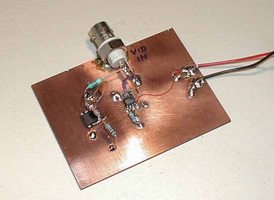
The kind of board you use depends on the application. Perforated, or ‘perf’ board, is best for lower frequency circuits, while copper clad is required for high frequency or sensitive circuits. There are several ways to secure components to the circuit board depending on the type of board. Perforated circuit boards allow you to mount the components on one side, while making connections on the other (sometimes using the leads of the components to make the interconnections). Copper clad board is generally used as a ground plane, while components are mounted "dead bug" style (usually upside down, hence the term dead bug) on the board with interconnections made "in the air" above the board. Otherwise isolated ‘islands’ are cut out of the copper, forming traces and mounting pads for components. This is fairly easy to do with a sharp razor and some patience. When actually building the circuit I generally place power connections or busses first, then start adding components from input to output. I check for short circuits often as I go along. Shorts are much more difficult to find after the board is completely stuffed. Pay attention to the pin locations of ICs, it is easy to get confused where pin 1 is when you turn the board over to solder connection on the backside. I usually mark pin 1 of ICs on both sides of the board as a reminder. Input and output connections (also known by the technical terms ‘gozintas’ and ‘gozoutas’, respectively) are also a consideration. Most circuits will have some sort of connectors to hook up other pieces of equipment such as power supplies, antennas, monitoring equipment, recording equipment or audio amplifiers. As usual, the type of connector used depends on the purpose of the connection. DC and low frequency inputs are generally banana jacks or screw terminals. High frequency inputs and outputs require BNC type connectors. Input and output connectors are generally mounted on the chassis, but I often mount connectors directly to the circuit board when building prototypes and sub-circuits. Connections between components, connectors and subsystems are usually done with the leads of the components themselves or with wire. I use solid-core wire for connections that are not going to move, otherwise I use stranded wire. The stranded wire can be flexed many more times before breaking. A good source of stranded wire is computer ribbon cable. Ribbon cable is usually 26 gauge stranded, very useful for prototyping circuits. Once the circuit is running
and debugged, it should be mounted in a chassis, or at the least the circuit
board should be mounted on standoffs. This will keep the board physically
stable while you experiment. Reprinted from:
|