| |
|||
|
|
|
Related Products: Society for Amateur Scientists
|
![]() Sponsored by:
Sponsored by:

Circuit Debugging Toolsby Paul Dito Regardless of how careful I am while constructing a prototype electronic circuit, I am always a bit surprised if the device works the first time I apply power. Most circuits of interest to the amateur scientist are going to be complex, with many connections between components. The chances of a wiring error are fairly high. Before you can build and troubleshoot your new prototype there are some very basic diagnostic tools you should have on hand. Obviously the more tools you have available, and the more sophisticated these tools, the easier the troubleshooting. Since this column is targeted for the amateur scientist, I'll assume the project is on a limited scale, and therefore describe how to put together a functional test bench with a minimal investment. Since all electronic circuits require a power source to supply voltage and/or current, fundamental tools include the voltmeter and the ammeter. The voltmeter is used to measure the potential voltage between two points in a circuit and the ammeter measures the current through a single point of a circuit. Voltmeters and ammeters are usually combined into one instrument with an ohmmeter for measuring resistance. The meter is connected to the circuit using two leads. For voltage measurements the leads are connected in parallel to the potential, while the current measurements are made in series (ie the circuit is broken and the meter connected in the current's path). In the case of voltage and current measurements, the meter is passive and has a small effect on an active circuit. Resistance measurements are taken with the circuit's power turned off. The meter supplies it's own current to make the measurement, hence there should not be any other power source connected to the circuit because it would confuse the reading.
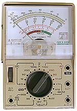
The primary advantage of the VOM is the electro-mechanical meter itself. The meter will respond to small, rapid changes in voltage or current. This can be useful while troubleshooting an intermittent circuit. Digital meters tend to have "smoothing" features to keep the value being displayed stable, and this can fool you into thinking a circuit is working properly, when in fact it is not. When using an analog meter, you must tell the meter what range of values you expect to measure before you attach the probes to the circuit. This allows the use of the full meter movement, whether measuring millivolts, or hundreds of volts. This is a minor inconvenience, and in some cases can be an advantage. DMMs that select the range automatically will be fooled by a voltage that is changing. It will scale to one range, the voltage will change, the meter will rescale, and the display will never stabilize.
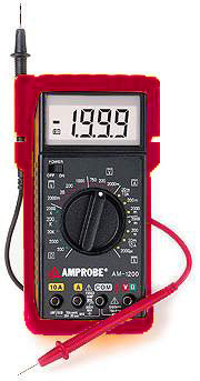
Beyond those two issues, the advantages of DMMs are many. They often have other features, such as the ability to test transistors and diodes, and functions to measure capacitance. They usually include an audible continuity checker. This can be invaluable for tracing connections on a prototyped circuit because you don't need to look at the meter to make a measurement. The meter looks for a low resistance between the test probes, and produces a tone if the two points are electrically connected. For either type of meter, the more you spend, the more features and accuracy you get. You will want to consider a meter that has different types test leads, or else purchase them separately. The most useful are the kinds with alligator clips or small spring loaded hooks so you can physically attach them to the circuit, thus freeing up a hand. Try to avoid less expensive meters that have leads permanently attached. Another useful tool is a variable power supply. While many circuits can be powered by batteries, it is much easier to have a line powered supply for prototyping. Most supplies allow you to control, or at least monitor the current fed into a circuit. If you plan to experiment with analog circuits a dual, or split, power supply is recommended as most analog circuits require a negative voltage for biasing purposes. I'll include a schematic for a simple dual power supply in the next column. A signal generator is not a necessity, but it makes prototyping and debugging considerably faster. A signal generator can be used to produce square waves for testing digital circuits, and it simplifies analog development by allowing you to build and test one stage of a circuit at a time. A clean, accurate signal generator can be expensive, but a reliable audio frequency generator is relatively easy to construct. After we build the dual power supply, I'll describe plans for an inexpensive function generator. Once you have your basic test equipment together, you'll want to round out your bench with various cables and patch cords to connect the instruments to your DUT (Device Under Test). Most test equipment has two types of connections available for input and output. Low frequency and DC ports use banana jacks, or simply binding posts (or both combined). Higher frequency equipment will have either RCA jacks, or BNC-type twist and lock connectors to connect shielded coaxial cable. "Coax" has a mesh screen surrounding the signal wire to prevent your equipment from emitting or picking up stray signals. Jumper wires with small alligator clips at either end are handy to have around also. You will also want to start stocking your "junk box" supplies. Most electronics hobbyist will salvage various components from discarded equipment, or past projects. It takes time to learn which components are valuable and worth storing. When I'm ordering parts for a prototype, I will often order several extras, in case one is damaged during construction, or fails later. Otherwise, the spare parts go into my junk box. Other necessities include hand
tools (needle nose pliers and wire cutters for example), a soldering iron,
and a breadboard. Find a well-lighted corner and start setting up your
bench. Reprinted from:
|